| |
Convert a miniQ into a LSE miniQ
Description: This tutorial shows you how to convert a standard DFRobot miniQ robot into a LSE miniQ, covering every step from hacking the robot to uploading the Arduino software.Keywords: miniQ, LSE, Arduino, swarm, olfaction
Tutorial Level: BEGINNER
Next Tutorial: Load the default settings to the LSE miniQ
This tutorial shows how to hack a DFRobot miniQ into a LSE miniQ robot developed for swarm olfactory experiments.
Contents
Overview
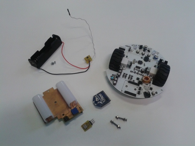
For this hack you'll need the following items:
DFRobot miniQ robot
- LSE miniQ expansion board
- LSE miniQ power board
- LSE miniQ Arduino software
- XBee module (actually you need at least 2, one for the computer!)
- 18650 battery
- Single 18650 battery holder
- e2v MiSC 5524 breakout board
- 3 pin header
- 2 pin header (x2)
- Jumper
- 33Kohm 0603 resistor (x2)
Note: If you would like the schematics to any of the hardware in these tutorial send us an email! |
Build a LSE miniQ
Hack the miniQ board
The first step requires you to desolder some unnecessary parts which will make room for the LSE miniQ expansion board.
Step 1
Desolder the 2 LDRs (in front of KEY1 and KEY3) and the orange potentiometer (W1) on the miniQ.
Step 2
Solder 2 pin headers in place of the old LDRs and place a jumper on the header located in front of KEY1.
Step 3
Solder a 3 pin header in place of the old potentiometer (W1).
Optional Step
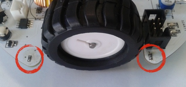
You can change the two resistors next to the right wheel for 33Kohm in order to dim the blue LEDs under the robot down. This will reduce the power consumption while improving the localization with the camera.
Mount the LSE miniQ power board
Step 4
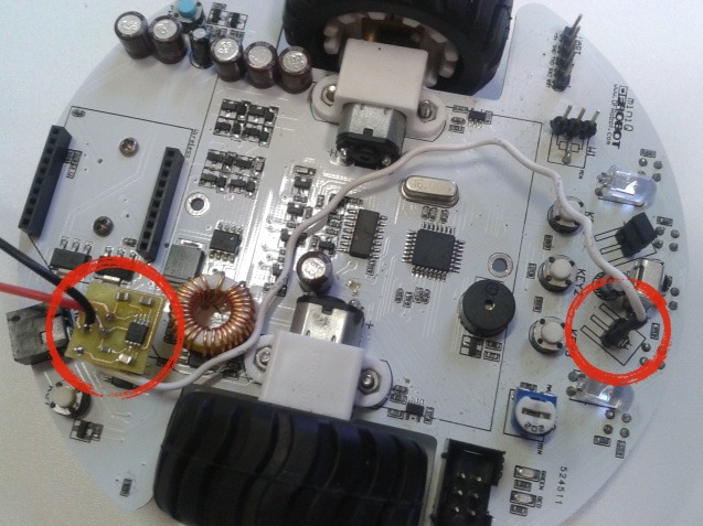
Solder the terminals of the 18650 battery holder to the LSE miniQ power board and plug it to the miniQ battery header. Connect the output of the LSE miniQ power board to the pin which is further away from the IR receiver on the header you soldered in front of KEY3.
Mount the LSE miniQ expansion board
Step 5
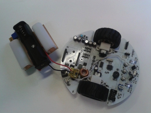
Insert the screws that were previously being used to secure the 4 AA battery case to the miniQ in the two holes on the LSE miniQ expansion board. Screw the 18650 battery holder to the LSE miniQ expansion board.
Step 6
Put the LSE miniQ expansion board in place and secure the screws.
Mount the e2v MiCS 5524 breakout board
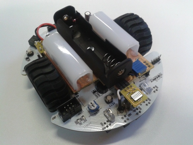
Step 7
Connect the e2v MiSC 5524 breakout board to the miniQ expansion board.
Download the software to the LSE miniQ
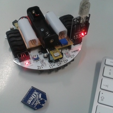
Step 8
Download the LSE miniQ software from...
Step 9
Connect the LSE miniQ to a computer and open the miniQRobot.ino file on your Arduino IDE of choice. Compile and download the software. Don't forget that the XBee module should be not installed (in both the robot and the adapter).
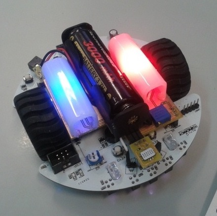
And that's it!!! You have finished building your own LSE miniQ robot. Install a 18650 battery, the LEDs should turn on immediately. You can turn the robot on by pressing the blue button (PW_ON). The robot should beep twice on powering up. The green LED should flash every second if everything is ok. If the red LED turns on it means the battery is getting low.
You can go on to loading the default settings to your LSE miniQ.


